Text:/ Scott Willsallen
All digital audio systems work by converting sound waves in air into a digital signal. This digital signal is then processed, stored, or both, and finally it is converted back into sound waves in air. The first step of the process is capturing the sound by a transducer, for example a microphone; this microphone transforms the sound into an electrical signal ‘analogue’ to the sound waves in air. This analogue signal is called a continuous signal since it reflects the sound wave in a continuous manner in time. Digital systems work with signals at certain intervals in time; these signals are called discrete signals. Continuous signals are transformed into discrete signals by two processes: time sampling and quantisation.

TIME SAMPLING
Time sampling is defined as the process where a continuous signal is measured or sampled at regular time intervals. The frequency at which these samples are taken is called the sample rate and is usually expressed in Hertz (cycles per second); some well known sample rates are the sample rate of the CD (44.1kHz), and the DVD (48kHz). Higher sample rates yield better results at capturing higher frequencies and avoiding frequency aliasing, as explained in the following paragraphs.
Henry Nyquist published a paper in 1928 that became the basis for digital audio theory. In this paper he described the relationship of the sampling rate to the maximum frequency that can be sampled in a system. In brief the maximum frequency that can be sampled, also called the Nyquist frequency, corresponds to half the sample rate. When a signal with a frequency higher than the Nyquist frequency is fed into a system it will produce frequency products folded around integer multiples of the sampling frequency, the relationship of the new frequencies to the input frequency is given by the formula:
Fa = ±NS±F and N = 0,1,2,3…

Where: Fa are the new frequencies resulting in Hz
S is the sampling frequency in Hz
F is an input frequency in Hz
N is an integer
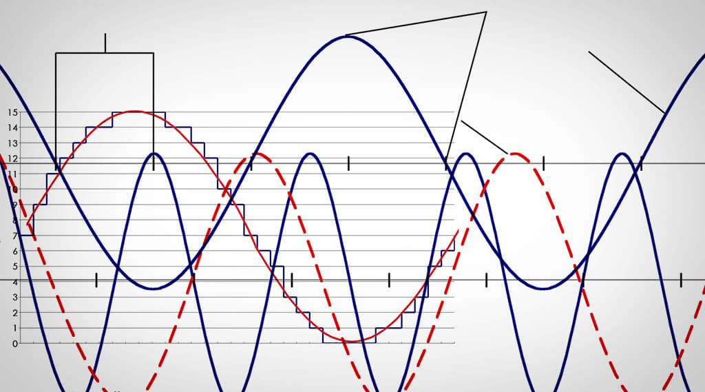
For example, if we record a signal with a frequency of 23kHz on a system with a sampling frequency of 44.1kHz we will get frequency products occurring at: ±21.1kHz, ±23kHz, ±65.2kHz, ±67.1kHz, ±109.3kHz, etc. If we subtract 21.kHz from 2 kHz we can see that this situation will produce an aliased artefact with a frequency of 1.9kHz. This problem can be avoided by adding a low-pass brickwall filter prior to the conversion. This problem can be encountered in the analogue-to-digital conversion as well as in the digital-to-analogue conversion.
The following figure further develops this concept.
QUANTISATION
The other process involved in transforming electrical analogue signals into digital signals is called quantisation. Quantisation can be defined as the process of assigning discrete values to the amplitude values of a continuous signal. The number of different discrete values a continuous signal can take is defined by the bit depth; the bit depth is the number of binary digits the maximum value can have. The maximum number of different values that can be represented by a certain bit depth including zero is given by: 2n, where n is the bit depth. For example a four-bit system will have a maximum value of 1111, which in decimal notation is 15, and can represent 16 different values including zero.

DYNAMIC RANGE
The dynamic range of a system increases with greater bit depths. The signal-to-noise ratio (SNR) is given by the following equation, adding approximately 6dB per bit added.
SNR(dB) = 1.76 + 6.02k
Where SNR is the signal to noise ratio, and,
k is the bit depth.
QUANTISATION ERROR
Higher bit depths also result in smaller quantisation errors. The quantisation error is the difference between the amplitude of the continuous signal compared to the amplitude of the discrete value signal. The maximum quantisation error corresponds to half of the quantisation step value. The shape of this quantisation error is closely related to the input signal, for complex signals the quantisation error will be randomised and its effects will be negligible. For periodic signals, e.g. sine tones, the quantisation error could result in transforming the sinusoidal (sine) wave into a square wave, presenting odd harmonic distortion; the effect will be clearly audible and unpleasant.
DITHER
A common method to avoid quantisation errors is by the addition of dither. Dither is a low level noise signal (usually white noise) added to the signal to be coded prior to quantisation. The addition of dither can help in reducing the effects of quantisation error of periodic signals by randomising the quantisation error, avoiding audible unpleasant distortion. For example, when a sine tone that does not vary greatly in level is input into the system without dither the resulting coded signal will be a square wave signal, with odd harmonic distortion, which is very audible and unpleasant to the ear. Dither takes advantage of a process called pulse width modulation; when adding dither to the input signal the resulting coded signal will be contained within a series of ‘pulses’ or changes between two quantisation values, these pulse fluctuations will vary in width following the shape of the original signal. This process will add some low level random noise and at the same time remove the harmonic distortion. In the end the ear will average the pulse width modulation and hear the original signal within the noise, the resulting low level random noise is far more pleasing to the ear and less audible than the harmonic distortion.
Dither is also used to reduce the quantisation error when a low level signal is introduced into the system. A signal with an amplitude smaller than the quantisation step would result in a signal ‘invisible’ to the system; adding dither with an amplitude of one third of the quantisation step will result in making the signal ‘visible’ to the system. The effects of dither are illustrated in the following figure.


A Pulse Code Modulated (PCM) signal refers to a signal that has been time sampled and each sample has been coded with a number corresponding to a set of discrete values (sampling and quantisation).
BIT RATE
The bit depth and sampling rate will determine the bit rate of the digital audio obtained and ultimately the size of the resulting file. The bit rate of a digital signal is obtained by multiplying the sampling frequency by the bit depth and then by the number of channels, this will give us the number of bits per second. For example a Compact Disc has a sampling rate of 44.1kHz, a bit depth of 16 and a channel count of 2, resulting in a bit rate of 1.4112 mega bits per second (44,100 x 16 x 2).
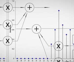
SAMPLE & HOLD
It is important to briefly describe another part of the system that transforms the audio into a digital signal. This circuit is called the sample and hold, this circuit delivers the audio to the analogue-to-digital converter. The sample and hold obtains a sample of the amplitude at a specific time, dependent on the sample rate, and holds this value while the analogue to digital converter calculates this value. An overview of the input and output of a digital audio system is shown in the following figure.

Finally, it is important to note that there can be errors introduced by imperfections in the circuitry of the sample and hold. Errors introduced by variations in the sampling period are called jitter, this happens when the timing of the sample and hold is not constant resulting in amplitude errors. Another error in the sampling process happens when voltage drops occur in the hold circuit of the sample and hold. These voltage drops are called droop and also result in amplitude errors.
With this we conclude the first part of the tutorial series on digital audio. In the next issue we will be discussing Digital Signal Operations and the associated latencies, as well as digital audio storage and typical storage media with their corresponding bit rates.
Scott Willsallen is the director and principal consultant of Auditoria P/L. Scott has completed a Masters with Honours in Audio Design Science at the University of Sydney.


RESPONSES