
HDMI Demystified
Get to know HDMI a little better and you can be best of friends.
29 June 2009
Text:/ Rod Sommerich
HDMI is an abbreviation for High Definition Multimedia Interface; a digital video connection standard for transmitting uncompressed digital video and audio signals for consumer and prosumer equipment. It’s a standard created by a consortium of manufacturers, including Hitachi, Matsushita (Panasonic), Sony, Philips, Silicon Image, Thomson (RCA) and Toshiba, and began shipping around 2003. It arose as a response to the introduction of new high-resolution products for home and non-professional use. Interoperability and consistent performance were needed for the high-resolution digital signals produced by Blu-ray, HD-DVD, computers and media centres, hard drive recorders, servers, HDTV set top boxes and other devices offering resolutions up to 10 times higher than standard video resolution. The original HDMI (v1.0 through to v1.2) carried audio and video signals up to 1920×1080 pixels or computer signals up to 1920×1200 (WUXGA) which are around 165MHz. The later HDMI v1.3 standard allowed for up to 340MHz, which caters for resolutions up to WQXGA (2560×1600), while the recently-announced HDMI v1.4 adds bi-directional audio and ethernet capabilities.
HDMI transmits video, audio and metadata on a single connection, with a ‘hot swap’ capability that allows it to be connected and removed without damaging the equipment or the need to restart devices. The benefits of HDMI lie in the multiple signals available and the near-perfect transmission of the signal in a digital format. The standard also allows for different digital video formats, including RGB and component, and audio that includes formats with up to eight channels, with support for 192kHz audio, multiple language support, Dolby and other high quality audio standards. Metadata is the information associated with the video content and includes such capabilities as device control (Consumer Electronics Control or CEC), screen resolution negotiation (Enhanced Display Data Channel or EDID), content and copy protection (High-bandwidth Digital Content Protection or HDCP), and Digital Rights Management (DRM).
VIDEO
The HDMI video channel carries either sRGB (sync Red Green Blue) or YCbCrb component video, at either 4:4:4 or 4:2:2 sample rates (see the Component Video box for more information). The advantage of using digital component signals in HDMI is the quality of the reproduction and signal integrity of these technologies over short distances. HDMI digital signals are not as susceptible to electrical interference as analogue and the picture quality does not have noise in the blacks often seen in analogue. HDMI does have some minor disadvantages, including its short signal transmit distance, connector integrity and durability , and the complexity of the cables.
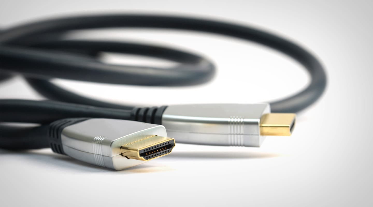
The HDMI connector is similar in appearance to a USB connector, but has more connections, including a hot swap conductor to allow for smooth connection and disconnection during equipment operation. While the connector is certified for over a million insertions, they are still susceptible to physical damage when the cable termination is flexed, run around acute angles or dramatically twisted during handling.
HDMI cable has 19 conductors which are sorted into pairs twisted at different twist ratios to reduce crosstalk – similar to Cat5e or Cat6 UTP cable. Consequently, good quality cables can be expensive and fragile. Multicore cables are not ideal for rough handling in domestic environments as they’re easily damaged and can’t be joined or re-terminated in the field. The cable doesn’t handle acute pressure or damage from being walked on, driven over by trolleys or vehicles on a frequent (or even occasional) basis and can fail without warning after that sort of abuse.
Unlike DVI and DisplayPort, which have cable retention systems to prevent the cables falling out of devices, the standard HDMI connector has no locking mechanism. Some HDMI cable manufacturers offer a proprietary locking system but these vary between suppliers and aren’t available on all devices or cables. One of the more popular locking systems uses a single retention point in the top centre of the connector similar to a VGA or DVI locking screw.
At 1080i, HDMI signals can be transmitted around 10m on an HDMI cable – depending on the cable quality and the signal resolution, transmission distances can vary significantly. At higher resolutions, like 1080p, the distance the signal will safely travel on an HDMI cable is reduced significantly. It is recommended to use good quality cable and consider using a signal extension system for runs over 10m. The choice of system depends on the application, budget and environment.
- 10m to 60m – HDMI cable booster
- 30m to150m – Balun and Cat5e/Cat6 Shielded Twisted Pair (FTP) cable
- 100m to 10km – Optical fibre
STRETCHING THE FRIENDSHIP
HDMI signal boosters reclock or resynchronise the relationship between the different signals in the cable. The cable pairs are twisted at different twist ratios to stop crosstalk between pairs, but different twist ratios mean that the pairs are different lengths, causing skew between the data packets over longer cable runs. HDMI boosters are placed at the destination to re-synchronise and equalise the signal levels so they arrive at the display at the same time.
The most common solution for extending HDMI runs are active HDMI balun systems that send the signal over STP Cat5/Cat6 cables. These balun systems work over runs of 25m to 150m. They change the impedance of the HDMI signals to match the Cat5/Cat6 cable, with the impedance changes reversed at the receiver end. Active or powered versions boost the signal level to allow it to be sent on longer runs. Balun systems are popular because Cat5/Cat6 cables are easy to terminate in the field during installation and are much lower cost than HDMI cable of similar length. It’s also easier to install these types of cables in conduits because of the smaller connector and ability to work over long cable runs. Cat5 /Cat6 cables are readily available from electrical or computer suppliers and can be terminated, repaired or replaced quickly and economically in the field.
Fibre optical systems are used on runs over 100m, and although more expensive, they are also more secure and are not susceptible to electrical interference from mains or other devices. These systems are available as either prefabricated cables with HDMI ends or as separate senders and receivers which accept separate fibre connections for LC, ST or other fibre systems.
The HDMI video channel is extremely similar to DVI and similar to the DisplayPort video standard. All three use similar video transmission technology and content protection systems, which allows for passive conversion between some of these standards. These adaptors are relatively inexpensive and simple to use. There is no signal conversion required when interconnecting the video portion of DVI, HDMI and DisplayPort once. It is not recommended, and often not even possible, to convert signals more than once in a cable run, due to minor incompatibilities between the standards. If more than one change is required in a signal path then active conversion is usually required. As DVI does not have an audio channel, active conversion and separate audio paths are required when combining or extracting audio between HDMI and DVI systems.
“”
Balun systems are popular because Cat5/Cat6 cables are easy to terminate and are much lower cost than HDMI cable of similar length
COMPONENT VIDEO
Component was introduced around 1982 in the Sony BetaCam and the JVC MII camera systems and heralded the start of high quality compact video recording and production in the broadcast industry. Prior to component, all the sync, colour and luminance information were combined into a single Composite signal. Composite has limited bandwidth, and fine detail can appear as a ‘beating’ or false colour on fine detail in an image. Component technology eliminates this type of problem by using separate detail and colour signals, thus providing a much higher bandwidth.
The YCbCr format derives its components by processing the original RGB image to remove some of its (mostly) redundant content. Y = luminance (the white or intensity part of the image), Cb = Blue minus Y and Cr = Red minus Y. This is sometimes called YUV (which is closely related but not identical). Using these derived components, rather than the wider bandwidth RGB signals, allows a high quality signal transmission using a relatively small bandwidth. The original RGB signals are recreated at the receiving end by calculating the missing parts from the component data.
The numbers 4:4:4 and 4:2:2 indicate the ratios of samples used for each of the component signals. A system using 4:4:4 sampling takes equal numbers of samples of each component and therefore contains all of the original component information. Using 4:2:2 sampling, the system uses four samples of the luminance (Y) component, but in the same timeframe takes only two samples each of the relatively less critical Cb and Cr components. This technique substantially reduces the amount of bandwidth required to transmit the image, but means that the colour information is only updated at half the rate of the luminance information, and thus produces relatively lower quality images. Even 4:2:2 systems carry much more picture information than the older composite video format.
META METADATA
The Display Data Channel (or DDC) part of the HDMI signal carries metadata, which is information about the other data (video and audio) in the signal. This includes the EDID (Enhanced Display Data) channel which was released around 1994 to support VGA computer displays and allow automatic selection of a common display resolution between a computer and a display device. The system has a table of resolutions a display and device can support, and the necessary logic to select the highest commonly supported resolution between the two devices. This system has developed and been adapted over the ensuing years, and is now incorporated into many systems, including HDMI, DVI and DisplayPort. Sometimes on long HDMI cable runs, where the signal becomes too weak or unstable for the display to recognise the signal, the EDID is not read correctly. This can be resolved either by using an HDMI booster or placing an EDID generator at the display end of the path to generate valid EDID data for the display to use.
HDCP (High-bandwidth Digital Content Protection) was developed as a copy prevention system for HDMI, and subsequently implemented on DVI and DisplayPort as the preferred standard for the motion picture and video game industries. It has also been widely adopted by the consumer electronics industry for video and audio devices. HDCP negotiates a connection between devices to confirm the security of the content. It will not permit HDCP signals to be sent to devices which do not support HDCP or devices which may change or record the signal. If a signal path is not HDCP-compliant from end to end, the source device will send either a black image, white noise (snow), or a very low-resolution image to avoid the possibility of copying or a breach of copyright. HDCP will not permit a signal to be sent to devices that can record or convert the signal to other formats, or to devices such as component analogue equipment that doesn’t support HDCP.
One issue which has arisen recently is the inability of some domestic devices, such as Blu-ray players and set top boxes, to handle more than three or four displays which may be connected through a distribution amp or splitter. HDCP delivers a key from the monitor to the source to permit display. It’s possible to exceed the memory allocation of these source devices, such that no image will appear on the extra displays. The maximum number of displays can’t exceed the available memory in the source device (ie. its ability to store/hold keys). This is a common problem in retail environments where multiple displays are required to display the same content, but it isn’t a direct fault of HDMI or HDCP.
POWERPLAY
DDC (Display Data Channel) supplies a maximum of 50mA at 5V to allow devices to connect and communicate, even when one of the devices is not powered, and allows the EDID and HDCP information to be negotiated prior to the device starting up. While some low-cost passive Cat5 or booster extenders use the DDC to power their operation, it’s not recommended to draw too much current from the DDC, as it can damage the supplying device. It’s recommended to use peripheral devices with their own power supplies.
DEF TOUCH
In a time when manufacturers are looking for ways for us to buy more shiny new stuff, HDMI is exactly what it says it is: an uncompressed digital delivery cable for users who demand high quality content reproduction. Without doubt, some of the peripheral technologies it employs makes it more complex to use than analogue cables. Nevertheless, for all of its faults and shortcomings, HDMI is currently the most accessible and best all-round performing format available for uncompressed digital content delivery for prosumer, home and corporate audiovisual applications. HDMI does not replace professional alternatives, but it does deliver better images, sound and functionality over a single cable than that tangle of cables you may well have behind your hi-fi or equipment rack right now.
Roll on HDMI v1.4…
Rod Sommerich (CTS) is National Product Manager of Display Products for Amber Technology. Like Rod, all readers are welcome to pitch article ideas. Send an email to the editor, [email protected].

One of several types available, this proprietary version of the HDMI connector retains full connection compatibility while adding a single captive screw to ensure a reliable connection.


RESPONSES