
Text:/ Derek Powell
Every display device such as a monitor or a projector, is built to a particular specification. At its most basic, every display has a native resolution (like 1024 x 768 for an XGA monitor) but many devices may be able to handle a range of signal types. Some may be able to correctly display inputs ranging from VGA to full HD, while others are built only to handle a limited range of signal frequencies and resolutions.
It is that information about the capabilities of the display that is stored in its Extended Display Information Data (EDID) memory and shared with any video source, such as a computer, connected to the display. [See Hooking Up – the way it’s meant to be]. The concept of EDID is brilliantly simple, and in its originally intended role, it simply works brilliantly. However, once you have two or more display devices in a system with different capabilities (and hence different EDIDs), you can easily enter a world of hurt.
HOW DID WE GET EDID?
To step back in time; important specifications about the very earliest displays were simply printed in the handbook and the user would need to manually configure the source machine’s output to suit the display’s capability. As the years passed, display manufacturers started to use a fixed voltage on spare pins on the VGA connector to signal basic features about the monitor (like whether it was capable of handling XGA or higher resolutions). That allowed a certain amount of automation so that when a monitor was connected, the PC would sense from the voltages present on these so-called ID pins whether the monitor was capable of, say, VGA or XGA and choose which format to send.
This, my friends, was the dawn of plug and play but as more resolution choices evolved, along with colour space and so on, the plugs started to get smarter!
Instead of simply using fixed signalling voltages, manufacturers agreed to convert Pins 4, 11 and 12 on the D15 (VGA) connector to a serial communication protocol called the Data Display Channel (DDC) so that a range of information could be sent through the monitor cable to the signal source. Later, DDC evolved into the set of standards we know as EDID and this is now universally used with DVI, HDMI and Display Port connections.
WHAT DOES EDID LOOK LIKE?
EDID parameters are stored as a standard 128-byte data block on a chip embedded in the display. Once the cable is hooked up, information on native resolution, colour space, timing, and even the model number and date of manufacture of the display, is sent across a bi-directional bus to allow the source to send exactly right signals to match the display. EDID has since been extended for use with consumer electronics to include more information on everything from the kind of audio signals to the type of 3D processing that a display device supports.
You can download a piece of software for most PCs that enables you to view the actual EDID information read out from the chip. The EDID is just a set of hexadecimal digits that look like 6F 68 20 73 68 74 21 and so on, so most viewers helpfully provide an explanation of what each part of the data actually means.
YES, BUT WHY DO WE NEED IT?
Here’s the crucial part of the EDID story. Nearly every source device, from Blu-Ray players to PCs, can send video in literally dozens of formats – different resolutions, syncs, colour space – you name it.
However, a particular monitor or projector can only reproduce a certain sub-set of the possible resolutions and will have very specific requirements for sync type, timing, colour space and much more. If presented with the wrong signal, the display may output pictures that are too large, too small, horizontally or vertically distorted, too fuzzy, or – very likely – no image at all.
The source uses the EDID data provided by the display to decide what video to send.
The exchange of data happens when the monitor is first connected in a process called handshaking, and source equipment can be very single minded about this. Not only could the picture be wrong if the EDID handshake is not successful, but the source may not output anything at all if it is not satisfied with the EDID it sees.

HOOKING UP – THE WAY IT WAS MEANT TO BE
It is important to understand how and when the source goes about harvesting EDID from the monitor. Let’s start with the simplest set-up – using a standard cable to connect a PC/video player to a monitor. This is the situation EDID was designed to address and almost always works.

STEP 1
The cable is connected between the source and monitor and the source is powered up. The source supplies +5 Volts to the monitor through the cable which automatically starts up the EDID circuit in the monitor, whether or not the monitor is powered.

STEP 2
The monitor’s EDID circuits send back a signal to the source by driving the special Hot Plug Detect pin in the cable to +5 Volts. As soon as the source sees a voltage at the hot plug detect (HPD) pin, it sends a request across the I2C serial link requesting the monitor send the 128-byte data set.

STEP 3
The monitor’s EDID chip sends the stream of data back to the source across the DDC pins in the cable. The data includes not just the ideal configuration that matches the monitor’s native resolution, but also any other standards that the monitor can display.

STEP 4
The source reads the data, configures its display settings to suit and outputs video with the correct resolution, timing, sync polarity and colour space to match the ideal configuration or, if the user has instructed otherwise, to match one of the other useable standards.
Hallelujah! Everything works and the monitor is now displaying the output in the best form it can handle.
Image from Extron’s white paper, EDID: A Guide to Identifying and Resolving Common Issues
SO WHY DOESN’T IT ALWAYS WORK?
Even in a simple situation, a couple of things can go wrong. First, it may be that the source is only capable of outputting a limited range of standards and the monitor can’t display any of them. In this day and age, this is pretty unlikely, but if one or other component is truly out of the ark, you’ll simply have to change it to something more compatible.
However if you find yourself with a mistimed, wrong size or missing image after the connection, then it is most likely the EDID information has not got through. A sensible check is to shut down the source and then re-start it to give the handshaking another chance and, of course, check the integrity of your cables. If things still aren’t right, then there are two possibilities.
Firstly, the information may have been corrupted, which can happen if the connection cable is too long. Just as long cables can cause problems with video transmission, the DDC channel can also fail if the voltage drops too far across long DDC signalling lines. Try a shorter cable and see if the problem disappears.
The other possibility is that there is simply no path for the EDID information. A classic case is connecting an analogue monitor via five (RGBH &V) coax cables rather than a D15-to-D15 cable. The necessary pins for the transmission of the EDID across DDC are simply not present in this connection so no handshaking can occur. The same situation can happen when using some types of signal extenders across such media as UTP (cat5/5e/6) cable or fibre. If the EDID is not transmitted correctly, or at all, then some sources will default to a very low resolution output like 640 x 480 VGA, while other sources may simply not output any video at all.
Fortunately, there are devices that are designed to connect into the signal path close to the source that will perform an EDID handshake to replace the missing information from display device and force the correct video output. Using an EDID emulator you can either capture EDID information from the display itself or switch to one of a number of preset standard EDID sets stored within the device. The video signals from the source-pass through the emulator and can then be sent to the display.
RECOGNISING EDID ISSUES
In our single source/single monitor example, there is little to go wrong, apart from missing the EDID handshake. But there are many other situations in professional AV systems where problems will always arise and EDID will have to be managed before you can get a system to operate correctly.
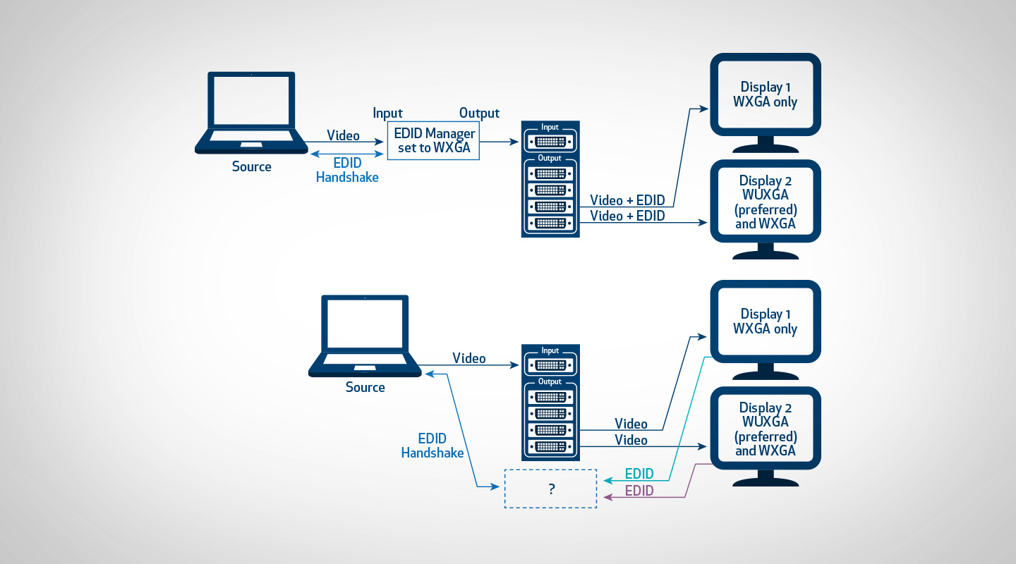
Stepping up in complexity, the next obvious example is where we have one source connected via a distribution amplifier to two monitors with different resolutions. Consider the situation in the diagram above. One monitor can display WUXGA and WXGA, while the other is limited to WXGA. If we wish to send the source to both monitors we can easily distribute video signals through a distribution amplifier but how do we arrange for an EDID handshake where we have one source and two different EDID information sets? A source can only output one resolution at a time and does not have the capacity to compare two choices and make a decision what kind of video to output.
Intuitively, I’m sure you can tell the best way to proceed. The best result will be to arrange the source to output the highest resolution common to both displays. If the source is arranged to output WXGA then both monitors will be able to display it.
However, if we simply connect everything up, the results can be unpredictable. With some brands of distribution amplifier, EDID might be passed through from monitor one; or EDID might be passed from monitor two; or there might be no EDID information passed at all! In two cases out of three the results will be unsatisfactory so it is clear we need to intervene and implement some kind of EDID management to make sure we get the best results.
In this case, a simple EDID emulator programmed to force our source to WXGA will solve our problem.

OVERCOMING COMPLEX EDID ISSUES
If we go just one step further in complexity, it quickly becomes clear that using a matrix switcher to connect a range of different sources to different monitors requires better management than a simple EDID emulator can provide.
To allow switching in any combination, we need to find the highest common resolution amongst the display devices on the output side, then ensure that common resolution is communicated to all the input devices. Of course, as well as resolution, we need to consider the effect of different colour space capabilities amongst the displays – some may only be able to handle RGB, not component video – and we may also need to instruct sources to send audio across HDMI if some output devices have internal speakers.
The best way to deal with switching issues is to ensure that the switcher has a system for EDID management built-in. Many matrix switchers are now capable of analysing the capabilities of the output devices that are connected by reading and comparing their EDID tables. The switcher will then apply an algorithm to come up with a ‘best compromise’ EDID it then presents to the connected sources so that they configure themselves correctly for all possible outputs.
For most situations this is a good start, but better EDID management systems allow the user to log-in to the switcher interface and manually set up each EDID parameter on every input. This permits the ideal results in a situation where one size does not fit all. For example, we may want some input sources to remain at the highest possible resolution if they are only ever switched to HD-capable monitors. A good management system will allow for exceptions to the general EDID rules for each input.
WHAT SHOULD YOU NOW KNOW?
- EDID is a block of hex data stored on a chip in all modern monitors and projectors.
- The data describes all the kinds of signals the monitor can handle, and which signals are preferred for best display.
- As soon as a display is plugged into a source (like a PC) the source reads the EDID data and sets itself up to provide the correct signals.
- Many modern sources (not just PCs but also DVDs and more) need to see a correct EDID signal or they won’t produce their best output (or sometimes any output at all).
- EDID works well when you plug a single display into a single source.
- Once any system has multiple displays or multiple sources, and especially if a matrix switcher is involved, you need to consider how to ensure the right EDID gets to the right source every time a switch is made.
There’s quite a bit more to EDID than we’ve had time for here, so I recommend you look up some of the web resources that are listed to learn more. Of course, once we iron out all the EDID issues between sources and displays, the next problem is dealing with HDCP – but that’s a horror story for another day.
MORE INFORMATION
Extron has a pair of excellent tutorials that go into EDID problems in some depth and are recommended reading. ShortURL: alturl.com/ry79j.
EDID Viewer. The simple EDID Manager Program from Extron lets you view the EDID information from connected equipment and is a good place to start to understand what EDID is about. You can download it (for PC only) from ShortURL: alturl.com/q4gxe.
Note: You will have to provide your name and email address to Extron for the privilege of downloading these files.


RESPONSES